Scientific Instruments and Equipments
scientifickart
SKU: OM-31028
Couldn't load pickup availability
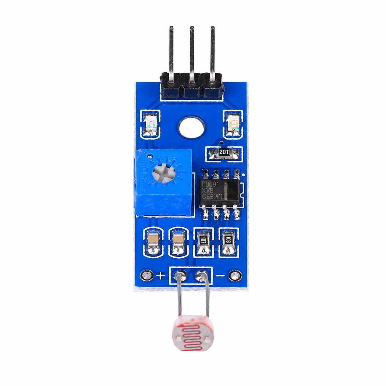
This is a standard Light Dependent Resistor (LDR) Sensor Module, widely used for light detection and automated switching applications. Based on the components visible in the image, specifically the 3-pin header and the 8-pin IC, here is the technical breakdown.
The board functions by converting the analog resistance changes of the photoresistor into a clean, readable digital signal.
Photoresistor (LDR): The component extending at the bottom. Its resistance decreases as the ambient light intensity increases.
LM393 Comparator: The black 8-pin surface-mount IC. It compares the varying voltage from the LDR against a fixed reference voltage.
Potentiometer: The blue trimpot with the crosshead. This acts as a voltage divider to set the reference voltage for the LM393, allowing you to manually calibrate the exact light threshold at which the sensor triggers.
Status LEDs: Typically, these modules feature two LEDs—one to indicate power and another to indicate when the digital output pin is triggered.
Operating Voltage: 3.3V to 5V DC.
Output Type: Digital Output (DO). It provides a clean HIGH (1) or LOW (0) logic signal.
Logic State: By default on most of these specific modules, the DO pin outputs HIGH in dark conditions and switches to LOW when the light intensity exceeds your set threshold.
Current Consumption: Typically around 15mA.
Comparator IC: LM393 (Wide supply voltage range, low power consumption).
Dimensions: Approximately 3.2cm x 1.4cm.
The 3-pin header makes it straightforward to interface with microcontrollers:
VCC: Connects to your power supply. Pro-tip: If you are interfacing this with 3.3V logic boards (like an ESP32 or STM32), power the module with 3.3V rather than 5V. The LM393 outputs a voltage equal to its supply voltage, so powering it with 3.3V ensures you don't fry your 3.3V-tolerant GPIO pins.
GND: Connects to common ground.
DO (Digital Out): Connects to any digital input pin. You can poll this pin in your main loop or, for more efficient code, attach a hardware interrupt to trigger an action exactly when the light state changes.
| Weight |
0.01 kg |
|---|---|
| Dimensions | 2 × 2 × 5 cm |
