Scientific Instruments and Equipments
scientifickart
SKU: OM-31011
Couldn't load pickup availability

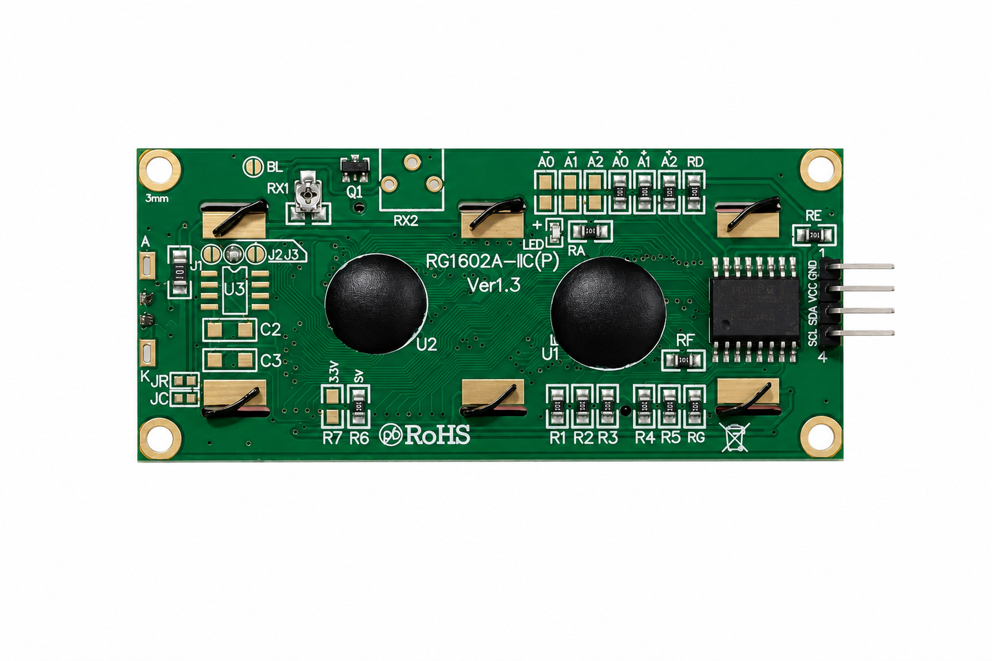
This component is a standard 16x2 Character LCD with an integrated I2C module.
The primary advantage of the I2C backpack is that it drastically reduces the wiring complexity. Instead of requiring up to 16 pins for a standard parallel connection, it allows you to control the display using just two data pins—making it an excellent choice for prototyping and displaying live telemetry or local sensor readings.
Here is the breakdown of its technical specifications and pinout:
Display Format: 16 characters wide by 2 rows high (32 characters total).
Operating Voltage (VCC): Typically 5V DC. (Note: If you are interfacing this with 3.3V microcontrollers, you will usually still need to power the VCC pin with 5V for the screen to be legible, though the data pins can often tolerate 3.3V logic).
I2C Interface Chip: Usually utilizes a PCF8574 or PCF8574T I/O expander.
Default I2C Address: Most commonly 0x27 or 0x3F (this depends on the specific batch and chip variant, and can be changed by bridging the A0, A1, A2 solder pads on the back).
LCD Controller: Industry-standard HD44780 (or equivalent).
Backlight: Blue background with white text (as seen in your image). The backlight can usually be enabled/disabled via software or by removing the jumper pin on the backpack.
Contrast Adjustment: There is a small blue potentiometer (trimpot) on the back of the I2C module. You will need a small screwdriver to adjust this to make the text visible.
The 4-pin header at the bottom of the module connects as follows:
GND: Connects to the ground of your microcontroller.
VCC: Connects to the 5V output of your microcontroller.
SDA (Serial Data): Connects to the I2C SDA pin on your board.
SCL (Serial Clock): Connects to the I2C SCL pin on your board.
| Weight |
0.035 kg |
|---|---|
| Dimensions | 2 × 5 × 10 cm |

